Author Topic: Greg's Bandit 400 Fuel Injection Project...  (Read 131274 times)

Offline greg737

  • Board Homesteader!
  • ***
  • Posts: 315
Re: Greg's Bandit 400 Fuel Injection Project...
« Reply #120 on: October 21, 2014, 01:11:30 AM »
ETA first start up?  :trustme:

I'm not sure.  I'm nearly finished with the wiring and I've been testing components to verify the connections.  Everything looks good so far.

The next step toward engine start-up will be initializing the Microsquirt ECU to begin the process of setting up the engine operating parameters.  I don't know if this process will go quickly or if it will take a while.  Since this is my second motorcycle fuel injection project I'm hoping to get through it quickly.

On the down-side I'm scheduled to work a lot next month so I might not make it to the garage as often as I'd like to.

Offline El Gringo

  • Board Homesteader!
  • ***
  • Posts: 127
Re: Greg's Bandit 400 Fuel Injection Project...
« Reply #121 on: October 21, 2014, 10:28:27 AM »
Looking good Greg, you've done a cracking job of getting all the parts located   :grin:

Offline greg737

  • Board Homesteader!
  • ***
  • Posts: 315
Re: Greg's Bandit 400 Fuel Injection Project...
« Reply #122 on: November 05, 2014, 12:54:38 PM »
Back in the garage today, working toward the first start-up of the Injection Project Bandit...

The first item on today's "to-do list" was something I've been avoiding for quite a while.  It was the small task of taking the oil pan off the bottom of the engine to inspect the bottom end.

Because the history of this Bandit is almost totally unknown to me I was apprehensive about what I might find.  A few months ago the oil sample that I took when I drained the Bandit's oil came back from its Blackstone Labs analysis with very good results, but I had no idea how long the oil had been in the engine when I bought the bike so there was still some doubt in my mind.

Things have gone really well today.  The oil pan turned out to be very clean with only a little dirty residue in the bottom.  The oil pick-up strainer screen contained only a small amount of debris most of which appeared to be the usual bits of silicon sealant that end up in the oil.  This is the usual stuff that comes from the engine's assembly at the factory.  Nothing alarming was to be found so I'm really happy.

With the oil pan and the oil pickup removed I had a very good view upward into the gearbox so I did a full visual inspection of every gear and every dog-tooth.  I used a mirror and a very bright flashlight to get a good look as I slowly rotated the gears.  I'm very happy to say that it appears my Bandit was never "speed-shifted" by a boy-racer.  All the gearbox components are free of damage. 

Even the "dogs" that engage second gear, which is the most commonly damaged gearbox part, don't show any damage or unusual wear.  In fact, there's very little wear at all in the gearbox.  I can only guess that the bike was never abused and the oil was always maintained/changed regularly. 

And, based on this evidence, I'm finally willing believe that the 19,000 miles that show on the Bandit's odometer are correct.

It was a very good day in the garage!
« Last Edit: November 05, 2014, 01:00:06 PM by greg737 »

Offline greg737

  • Board Homesteader!
  • ***
  • Posts: 315
Re: Greg's Bandit 400 Fuel Injection Project...
« Reply #123 on: November 07, 2014, 01:51:19 AM »
I spent today's allotment of "garage time" putting together a Manifold Absolute Pressure (MAP) sensor array. 

In a fuel injection system the MAP sensor measures the vacuum that is created in the intake tract during operation. 

The problem with the Bandit is that there's no central intake manifold to put a single MAP sensor on like a car would have.  This is how most fuel injection systems are configured.  But the Bandit 400 breaths in through individual throttle bodies (in case you haven't followed this entire build thread, I've converted the bike's original bank of Mikuni BST32s from carbs into throttle bodies).  Using individual throttle bodies means there is no central spot on the intake to place the MAP sensor and the Bandit's small, high revving cylinders produce a very jagged, jumpy vacuum that is basically useless.

Sometimes people working on do-it-yourself fuel injection projects will attempt to overcome this problem by running tubes from each of the cylinders to a small plenum that contains the MAP sensor.  This can help because it has the effect of averaging, combining and damping the individual cylinder's jagged, jumpy vacuum.

But I wanted to go a bit further toward solving this issue...

This circuit has a dedicated MAP sensor to measure the vacuum of each individual cylinder.  It takes these continuous inputs from the cylinders and only reports the vacuum signal from the cylinder that is currently pulling the most vacuum.  It uses high-speed switching diodes to do this operation on a millisecond-by-millisecond basis.

Here's what the circuit looks like.  There is a sensor for each cylinder (the top four sensors), and there's a fifth sensor that will act as a "constant barometric" sensor.  This fifth sensor will make it possible for the Microsquirt to correct fueling when I ride to higher elevations.
.

.
.
.
Most of the wiring is hidden below the sensors.  It's a relatively simple circuit, it only contains 5 switching diodes, 1 Zener diode, 3 resistors and 1 Op Amp.  I had to order the sensors but everything else, including the circuit board, came from Radio Shack.
.

.
.
.

.

.
.
.
Here's the circuit laid out on a circuit simulator app.  This simulator allows you to test how your circuit will work before you build it.
.

.
.
.
Here's the transfer function that these Freescale Semiconductor MPX4115 MAP sensors use.  It changes the engine's intake vacuum (measured in kPa) into a signal that ranges between 0 and 5 volts.
.
« Last Edit: November 07, 2014, 02:11:18 AM by greg737 »

Offline greg737

  • Board Homesteader!
  • ***
  • Posts: 315
Re: Greg's Bandit 400 Fuel Injection Project...
« Reply #124 on: November 07, 2014, 02:03:34 AM »
Tomorrow I'll be putting oil in the Bandit's crankcase. 

Then I'll begin turning the engine over without fuel or ignition.  This will be for testing of the signal generator (variable reluctance pulser) input to the Microsquirt.  This is the first step in setting up the ignition timing.
« Last Edit: November 07, 2014, 02:12:46 AM by greg737 »

Offline El Gringo

  • Board Homesteader!
  • ***
  • Posts: 127
Re: Greg's Bandit 400 Fuel Injection Project...
« Reply #125 on: November 07, 2014, 04:33:53 AM »
Fantastic work Greg  :clap:

Really enjoying the write ups

Offline greg737

  • Board Homesteader!
  • ***
  • Posts: 315
Re: Greg's Bandit 400 Fuel Injection Project...
« Reply #126 on: November 10, 2014, 02:25:00 AM »
Squeezed in some garage time today (Sunday).  I've got oil in the Bandit's crankcase and I'm turning the engine over.

The first step toward firing the engine is verifying that the Microsquirt (the Bandit's fuel injection ECU) is getting a pulse from the Signal Generator (Variable Reluctance sensor).  I'm using my laptop computer, hooked up to the Microsquirt's communications plug, controlling the Microsquirt with a software package called TunerStudio.

With communication established between the Microsqurit and TunerStudio I've done a couple of data-captures of the engine turning over.  For safety and to protect the fuel injection system's components I've taken out the fuses that supply electricity to the ignition coils, the injectors and the fuel pump so that none of the dangerous stuff has any power.

All I wanted to see today was whether the Microsquirt is getting a good trace from the Signal Generator.

Here's a screenshot of the TunerStudio program display after I took a "Tooth Log" of the Signal Generator. 

In a TunerStudio Tooth Log each of the blue lines indicates the time that has elapsed between each tooth on the trigger wheel as they pass by the Signal Generator.

.

.
.
.
My Bandit's (modified) trigger wheel has 5 teeth spaced out on the wheel as if there where 6 teeth (with one missing tooth).  In the do-it-yourself fuel injection world this wheel is called a "6 minus 1".  The missing tooth is the area of the trigger wheel that creates the extra-tall blue line on the Tooth Log.
.

.
.
.
This next picture is a screenshot from a TunerStudio "Composite Log".  The Composite Log tells whether the Microsquirt is configured correctly to read my 6-1 trigger wheel pulses.  The blue lines are the trigger wheel teeth going past the Signal Generator sensor and the red lines at the bottom indicate whether or not the Microsquirt has achieved "Sync". 

When the Microsquirt has "Sync" the red lines stop and this means that the Microsquirt now knows where Top-Dead-Center of cylinder #1 is.  When it knows this it is capable of controlling the Bandit's ignition system.

.

.
You can see that the red lines end pretty quickly, after only a couple of engine rotations, which means the Microsquirt is getting "Sync" very quickly.  This is great!  I can now move on to the next step on the way toward getting this engine running...

...just in time for winter  :duh:.
« Last Edit: November 10, 2014, 02:26:53 AM by greg737 »

Offline greg737

  • Board Homesteader!
  • ***
  • Posts: 315
Re: Greg's Bandit 400 Fuel Injection Project...
« Reply #127 on: November 10, 2014, 02:27:39 PM »
Today's discovery/revelation is that I'm a spoiled brat... when it comes to my expectations of the Bandit 400's electrical system.

Explanation

My first motorcycle fuel injection project was a 2005 Kawasaki EX250.  I guess I'm guilty of "looking down on my nose" at the EX250.  I've always assumed that its systems were all rather basic examples of late-1980's motorcycle technology and design.

Well, today I came to the realization that there's a point where the EX250 beats the GSF400. 

The EX250 has a headlight cutout relay that disables power to the headlight from key-switch-on until after the engine is started and power is coming through the rectifier/regulator.  The GSF400 does not have this feature.  I was spoiled by the EX250 and I just assumed that the GSF400 would have this technology.  Now I feel like a spoiled brat.

Here's what the Kawasaki EX250's headlight circuitry looks like:
.


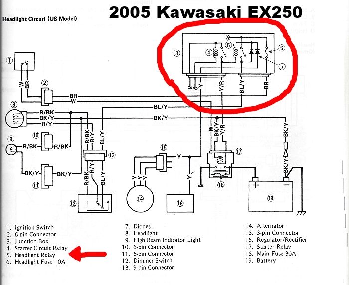
The most delicate moment in running a fuel injection system is cranking/starting.  This is because during those first few seconds you need the battery to provide power for all of the system's electrical needs: ECU power, Fuel Pump, Starter Motor, Ignition Coils and more.  The one thing you absolutely don't want is to have a large voltage drop in the system (this adversely affects all sorts of things).  Having the headlight power disabled during these moments is pretty important.

But I'm in luck because back when Triumph Motorcycles started building bikes with fuel injection they (Triumph's design team) didn't bother to add in a headlight cutout relay.  So the whole first generation of their fuel injected motorcycles are difficult to start and there's an aftermarket "plug-'n-play" headlight relay that was developed to cure the problem. 

This relay is designed to fit motorcycles with H4 headlight bulbs, which is what the Bandit has.  It will plug right into the Bandit's headlight in the headlight bucket.  With this modification the Bandit's headlight will stay off until after engine startup.  Then you have to flick the headlight switch to "bright" for a moment which activates the relay and the headlight will operate normally.

I ordered the item today, it should arrive in a few days.  Until then I'll be doing my work on the Bandit with the headlight unplugged.
« Last Edit: November 10, 2014, 02:31:54 PM by greg737 »

Offline greg737

  • Board Homesteader!
  • ***
  • Posts: 315
Re: Greg's Bandit 400 Fuel Injection Project...
« Reply #128 on: November 14, 2014, 11:41:12 PM »
It Runs!!! :banana: Holy crap, It runs!!!

Tonight the fuel injected Bandit 400 came to life for the first time.

Over the last few days I'd been having a bit of trouble getting the Microsquirt ECU to "play nice" with the Suzuki OEM trigger wheel + pulse generator, all of my test results and data-logs looked horrible.   But tonight I had a sudden brain-storm and figured out what the Microsquirt wanted.  I made a small change to the teeth of the trigger wheel.  I took a dremel and cut the width of the teeth down from 13mm to 6mm which resulted in a pulse profile that the Microsquirt loves.


The Bandit starts up right on the button, no hesitation at all.

I let it idle for a while so it could warm up and the bike appears to be "all systems go": 

- No fuel leaks, the Honda TRX500 fuel pump whirrs along happily with the Ninja ZX-6R injectors firing away,
 
- no coolant leaks,

- all 4 individual header pipes heat up together (so I know the Honda CBR600 coil-on-plug sticks are firing on all 4 cylinders),
 
- the electrical system is showing 13.7 volts when the engine is running meaning the Yamaha YZF-R1 rectifier/regulator is working properly,

- all the sensors reporting correctly, which means all the wiring was done right.

Sometime next week I'll be back in the garage to begin the tuning phase.  Before long it will be time to test-ride if the weather will allow it.

I will be taking some video of the bike soon and I'll post it here on the thread.
« Last Edit: November 14, 2014, 11:47:52 PM by greg737 »

Offline vintagemilano

  • TURBO TYPER!
  • **
  • Posts: 21
Re: Greg's Bandit 400 Fuel Injection Project...
« Reply #129 on: November 15, 2014, 04:04:57 AM »
That's pretty cool!
1993 GSF400
Cranbrook, BC, Canada

Offline El Gringo

  • Board Homesteader!
  • ***
  • Posts: 127
Re: Greg's Bandit 400 Fuel Injection Project...
« Reply #130 on: November 15, 2014, 07:25:09 AM »
 :clap: Absolutely awesome Greg

Offline Squishy

  • Board Homesteader!
  • ***
  • Posts: 417
Re: Greg's Bandit 400 Fuel Injection Project...
« Reply #131 on: November 15, 2014, 07:51:00 AM »
 :yikes:

Gotta say, didn't expect it to start right away!
Almost always something is wrong.
Great job, curious to see the video and ito hear sbout how it performs

Offline tubular

  • TURBO TYPER!
  • **
  • Posts: 20
Re: Greg's Bandit 400 Fuel Injection Project...
« Reply #132 on: November 15, 2014, 02:53:19 PM »
Congratulations Greg, though judging from your previous experience from the Kawasaki EX-250 conversion I had no doubt that this project would come along smoothly. You plan and execute professional and efficiently!

Offline greg737

  • Board Homesteader!
  • ***
  • Posts: 315
Re: Greg's Bandit 400 Fuel Injection Project...
« Reply #133 on: November 15, 2014, 05:40:24 PM »
Thanks Themis,

I can't wait to get back to work on it. 

My breakthrough moment was realizing that the teeth on the OEM Suzuki wheel were just too wide to make a Microsquirt's variable reluctance interface circuit happy http://www.useasydocs.com/theory/vr.htm (the wide trigger wheel teeth might be okay for the Bandit 400's OEM Denso Corp. ignition control system, but I can tell you they were definitely not good for a Microsquirt).  I can't remember if your Bandit 400 fuel injection project was fuel-only or if it included ignition control... you may remember reading in the Microsquirt/Megasquirt manual they (Bowling & Grippo) strongly recommend that the trigger wheel teeth be approximately the same width as the VR sensor pickup.  That was the change I made.

But as usual, garage time is limited.  The rest of November is tightly scheduled with a bunch of other things (work and family).

It looks like early December will be my next stretch of quality garage time.  Looking forward to it.

How's your Bandit?  We know who was the first one to fuel inject a B4 (I have to settle with being the first in the U.S).

Offline andrewsw

  • Board Homesteader!
  • ***
  • Posts: 598
Re: Greg's Bandit 400 Fuel Injection Project...
« Reply #134 on: November 17, 2014, 12:13:54 PM »
Wow! Awesome, congratulations!   :clap:

A