As posted elsewhere on this forum, the stock horn is a little lame when trying to command attention from folks doing everything else BUT driving attentively.

It would be nice to be able to bring them back to reality with a push of a button and I believe I have found that button. I recently got a Stebel Nautilus Compact Air Horn and just needed some time to figure out where and how to mount it. With the crazy winter weather (70’s & 80’s) it was hard to pass up riding opportunities

so the horn install got pushed back. It finally rained in Texas last weekend thus I began an odyssey of sorts, like only a/r people can

– here is how I did it.
The horn unit itself is quite small, self-contained and requires no hoses. It also comes with its own horn relay. The wiring to the stocker is not large enough to handle the load so using the relay is a must. I wanted to keep the stock horn in place, use the existing horn button on the handle bars and have the option to use both horns together or just the stocker.

There is some question about the air horn passing the state vehicle inspection process but by pressing a remote switch I can choose either mode.
With the body work removed it was time to find a home for this thing. I tried several locations and positions. I didn’t want to have to disconnect it for routine servicing like valve adjusts or fairing removal. The left side was better suited for the horn’s mounting bolt and also allowed for proper positioning with the trumpet openings aimed downward to ward off rain. There’s a tubular support bracket for the headlight and fairing assembly so I decided to make a mounting bracket that cupped the tubing. I found out that round surfaces don’t mate very will with flat surfaces and in addition – the horn unit needed to be tilted to avoid binding with other parts of the fairing assembly. A pipe nipple nearly the same diameter as the support bracket was used for mock-up purposes. The basic idea is shown in the photo below.
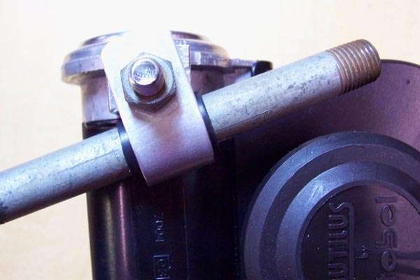
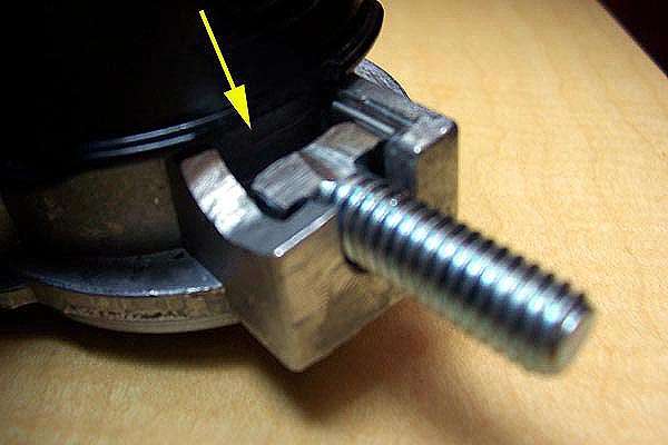
In order to have the mounting bolt positioned securely a radius had to be dremeled in the horn bracket that matched the pipe diameter. This also lowered the horn unit to clear the top of the fairing by a quarter inch or so. The head of the bolt needed to be ground off using a bench grinder (wear gloves).

It’s a good idea to have a couple of extra bolts handy in case you grind things ass-backwards.

Here is the horn bracket and bolt after modification.
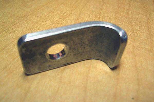
I made the mating bracket out of aluminum bar stock .75” wide by .125” thick. I chose it because I already had some laying around and figured it would be easy to bend. Using the pipe nipple and a vice I bent a nearly perfect radius to match. Then I drilled a 5/16” hole to match the bolt location – rounded the edges and patted myself on the back.

Doing it over again I would have used steel bar instead. What made for nice forming promptly deformed when I cranked down the mounting nut on the final assembly.

A couple of steel washers solved that problem but a steel bracket would have been perfect – I even have a torch for heating/bending and didn’t think to use it.
Anyway, here is the aluminum bracket I made.
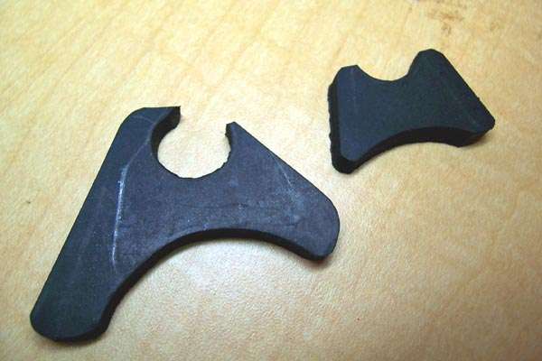
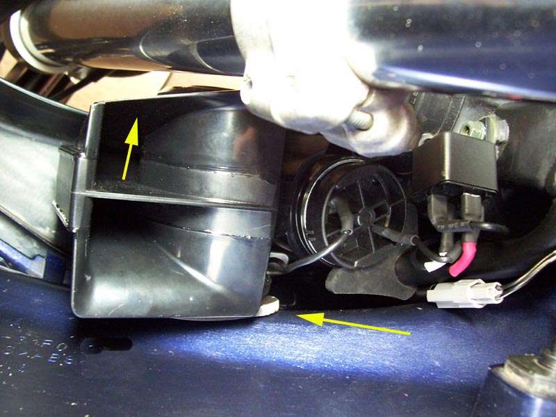
The next picture shows a couple of rubber mounting plates that I cut out after bolting the horn in position on the bike. They are used to stabilize the lower portion of the horn and prevent twisting around the tubular bracket. It will make more sense later on in the article but something is needed in addition to the steel bolt and bracket to eliminate all movement during operation. I used a very dense rubber mat about .25” thick and laminated the two pieces shown to form one. A thicker solid piece would have been better but again… I used what I had laying around. The radii match the horn unit and tube support.
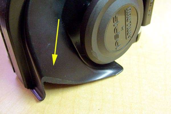
You will need to trim some of the horn trumpet to ensure clearance around the front forks during steering. Using a disk sander, I ground off about 3/8” at an angle that matched the fork travel. You may need less or more but be sure to do this before the final mounting. Check and re-check sufficient clearance is available several times and especially before you actually go ride. The plastic is pretty tough and doesn’t need any reinforcement after trimming. Here is the idea…
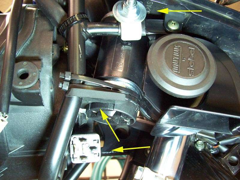
With all the pre-fab work done it was time to mount the horn in place. I used a thin piece of rubber around the tubular bracket similar to inner tube. This protects and provides better grip for the clamping bolt. You can see it better in the mock-up image. The steel washers provide more clamping power and I also used a nylock nut to prevent the thing from loosening due to vibration. The rubber mounting plate is visible at the bottom of the horn. This is secured with a couple of tie-wraps and really tightened things up. Another suggestion would be to use a screw type metal hose clamp. The only ones I had were too wide and too stiff so I settled for double wraps. Finally, there is a perfect mounting place for the horn relay – the bolt holding the headlight housing is long enough to accept the relay mounting plate. Enlarge the hole in the plate slightly using the proper sized drill bit. Again, notice how the horn is tilted slightly for clearance and the rubber mounting plate size determines the correct angle.
Now for the wiring part.


First, you must study the wiring diagram for YOUR bike very carefully. The wires I spliced into were based on wiring diagrams for my bike and yours may differ. I assume no responsibility if things go “poof” because you tapped into the wrong wire.

With that said, I poured over wiring diagrams for nearly three hours…
I couldn’t figure out how they designed the Bandit horn circuit. Two things helped though and the most important one was a COLOR wiring diagram as found in my Haynes manual. If nothing else, buy one for this reason alone. The second thing was to quit thinking things would be wired conventionally. Most circuits have the “hot” wire switched… the horn button should be on the positive side of the horn itself. It ain’t so on the Bandit – or my Bandit anyway.
Power goes to the horn first and then to the switch… a voltmeter confirmed this and things started to make a little sense.
You need to install a dedicated fused wire from your battery to one terminal on the relay. The fuse holder requires a 20 amp fuse. Wal-mart sells one for a couple of bucks that comes with 12 gauge wire. I ran 14 gauge wire for the horn circuit itself – the relay circuit can be 16 or 18 gauge due to the lower current draw.
Be sure to disconnect the battery before running your wiring to avoid shorts. Route the new hot lead along an existing wiring harness up to the front of the bike. Leave plenty of wire for final routing and splicing. This wire will go to the relay spade lug directly opposite of the only spade lug that is turned sideways from the other three. The sideways lug will need a short lead from there to the positive side of the horn. The wiring diagram that came with the horn will show four different ways of wiring based on keeping or replacing the original horn and whether the “hot” lead or “ground” is switched. The installation described here kept the stock horn and switched the “ground” wire.
The relay circuit wiring needs its own hot and ground wire. For a cleaner installation,

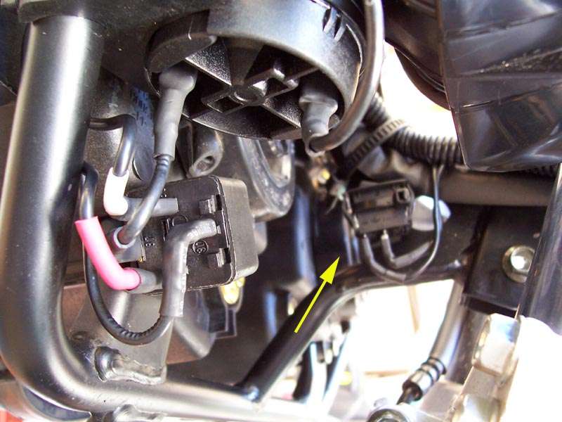
I removed the horn wiring harness from the stock horn and used a pick tool to unlock the spade lugs from the plastic bracket. Tie the two spade lugs together with a long piece of string and slide the wiring harness covering off. The hot lead to the stock horn was orange with a green stripe and I spliced a new wire on to that and eventually routed it to the positive relay terminal – the red heat shrink tubing in the picture below. The ground lead to the stock horn was also spliced into and eventually routed to a switch before continuing onto the last terminal of the horn relay - shown with white heat shrink. Make your splices somewhere in the middle of the stock horn wires but remember to offset them to avoid shorts. Use heat shrink tubing or electrical tape on the connections and be sure to mark which one is which. Using the string to pull the wires, slide the harness cover back over the entire thing and you should have two new wires emerging from the top and looking totally factory. The switch was a heavy duty rocker switch mounted with another rubber cushion and a nylon tie-wrap. This switch is only used to disable the air horn if needed so its location is not critical but I found a good spot on the headlight mounting bracket next to the wiring harness. The installation should look similar to this.
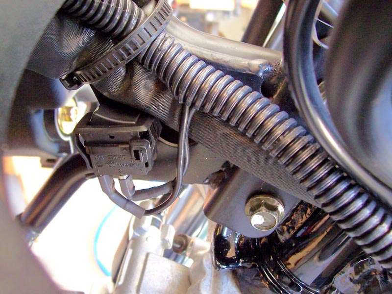
A close up of the switch location shows how nicely corrugated wire molding covers the new wires and adds a nice touch to what little wiring would show around the forks.

It also covered up some major screw-ups and unnecessary wire splices that you can avoid by reading this article.
I found the rocker switch and wire mold at Lowe’s but Wal-mart had similar stuff too.
The horn itself needs to be grounded. There is a fairing mounting screw that mates with the metal frame and the voltmeter confirmed this to be a good ground. One more short lead with a eye lug made for a clean wiring job and we’re finished. If you have any doubts about how correct your wiring is you can always hook things up temporarily while the leads are still long. If everything works, cut the wires to the correct length and make your connections. Here is one last look before putting the fairing back together.
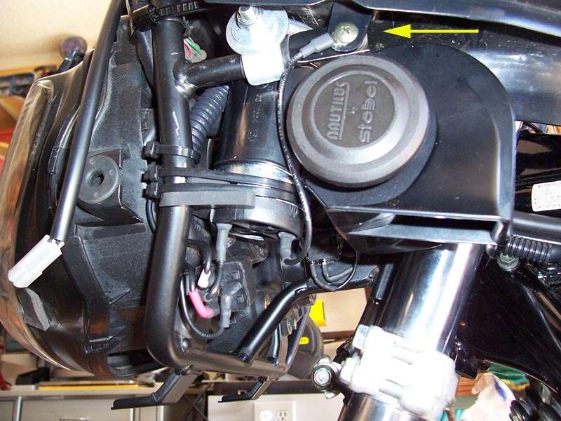
It doesn’t hurt to check clearances by periodically installing the outer fairing during the mounting procedure. I knew things were going to be close and they were. I added a piece of 1/4 inch foam weather stripping on the outside of the horn to keep any direct contact to a minimum. There ended up being a 1/8 inch gap so the foam wasn’t needed but it can’t hurt. The final picture is taken from underneath looking up and you can see the foam. You can also see how the trumpet horn trim job gave acceptable fork clearance.
Conclusion… THIS THING TOTALLY ROCKS!!!

I had a chance to try it out and it is freeking LOUD!!! By using the isolation switch you can really tell the difference between the two horns. Sometimes while riding with earplugs and wind noise you can’t even hear the stock horn – this baby will blow you away. It is rated at 139 db but that is measured 4” away from the unit. I was able to get a decibel meter and at 2 feet it pegged the meter (maximum possible readout available) at 126 db. By comparison the stock horn only puts out 104 db. At ten feet the air horn still put out 115 db which is nearly four times louder than the stock horn. This is one of the best $40.00 upgrades you can add to a bike and I highly recommend it. Hope you enjoyed the article and

for reading.


 Topic: Stebel Air Horn Installation (Read 17308 times)