Here's how I did mine - it's a repost from an earlier BanditAlley thread that got deleted in the last board crash. It relies more on mechanical application than electronic. It was written in response to a "Coolest Mod" thread and remains my favorite to date. Originally posted in December of 2004 on my Bandit 600 it also works well on my 2nd gen. 1200. For earlier models you'll need to find a different remote switch location.
>>>>>>>>>>>>>>>>>>>>>>
Inspired by “Hydrogen’s” post on the coolest Bandit modification I decided to add a garage door opener to my bike. Although the mini-remote fits nicely in a pants pocket it never seems to be handy and a real PITA to tote around all day. Now there are a lot of different ways to do this and no doubt some easier ones than described here but I wanted to share the method I came up with – just understand that in some circles I’ve been known to complicate a horseshoe.
There were specific criteria, which had to be met… after all this is a Bandit we are talking about so double-sided sticky tape on the fairing just wouldn’t do. It needed to be concealed in some fashion and not obvious to the casual observer. I did not want to drill or modify any aspects of the bike, especially the fairing even though it had plenty of room to play with. The remote itself needed to be accessible for the occasional battery replacement or code change. It also needed to be portable and/or removable without a lot of hassle since you may not want it available to less scrupulous folk. Finally, I didn’t want to add to any maintenance headaches. Bad enough you have to remove the gas tank to check the air filter. Not too much to ask, huh?
The idea was to hardwire a second switch to the remote in parallel so that either switch would activate the opener. By installing a receptacle on the remote, the switch wiring harness can be removed and the remote used in normal fashion. After scrounging around the shop I found all the parts needed - a bit of wire, a pushbutton switch (normally open type), heat shrink tubing, solder and a plug/receptacle assembly. Total cost shouldn’t set you back more than a sawbuck assuming you already have the opener. None of these items have specific part numbers and Radio Shack will have everything you need.
The hardest part was figuring where to attach the new switch wires to the remote. I am no circuit board expert but it was easy to see that the internal pushbutton on the remote had four posts on it. Jumping across two of the four should activate the circuit but I needed to find the correct two. WARNING #1: Garage doors can cause serious injuries – remove the battery from the remote, change the code and turn off the garage door to prevent accidental door movement. DISCLAIMER #1: Poking around a circuit board with wires and probes can cause shorts that will turn your remote into a lousy paperweight – do not touch any contacts other that the switch itself. DISCLAIMER #2: Do not blame me or anyone else on this board if you screw up Disclaimer #1. If you are still here, let’s get started.
Open the remote and remove the battery for now. You should see the internal PB (pushbutton) switch with four legs protruding into the circuit board. Using a continuity tester touch two switch legs while holding the switch down. An extra set of hands here goes a long way. Be careful that the tester does not give a false reading by touching the metal housing of the switch – just touch the legs. Checking all four legs (in pairs) should give you an idea of the switchable (on/off) legs. The switch on my remote had two pairs that completed the circuit when the PB was pushed.
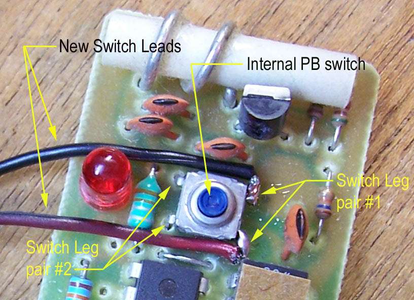
Knowing which legs are switchable is only half of the puzzle. One pair made the indicator bulb light up but did not activate the door opener. Placing a jumper across the leg sets with the battery installed, code set and door opener activated will determine which pair of legs you need to use. WARNING #2: Make sure the door is clear of vehicles, people and pets when performing this test. A pair of metal tweezers makes a good controllable jumper and remember to only touch the switch legs – nothing else. Momentary contact with the jump wire (tweezers) should start the door moving and a second momentary contact should stop it. These will be the legs you solder the new wires to.
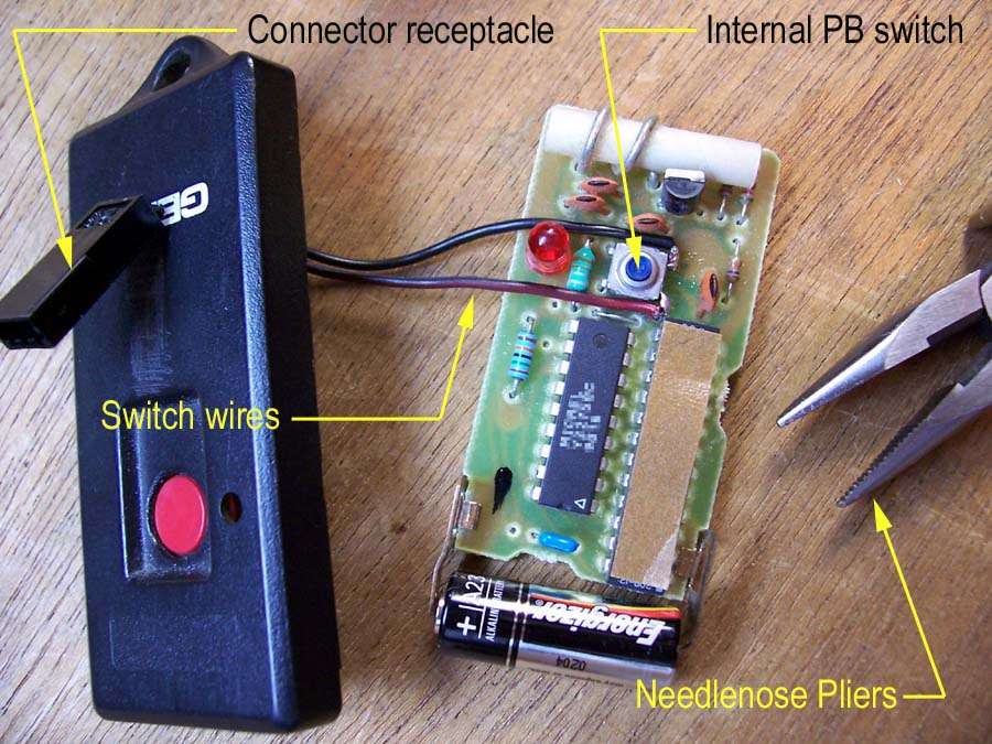
The next step is to drill some holes in the case for the new switch wires. The size will depend on the type of plug/receptacle assembly you choose to use. Insulated spade lugs would certainly work and cost next to nothing. I used a servo extension from a radio controlled airplane assembly because it was free and most importantly it had small stranded wiring that was ideal for fitting into the case. The length of wiring to the internal switch is sort of important….. too long and the case won’t shut – too short and soldering is difficult. Plan ahead as the receptacle’s location should not interfere with operating the internal PB switch when removed from the bike. Thread the wires through the case and solder the ends to the appropriate internal switch legs as determined above. To make this process easier I recommend pre-tinning the wire ends and switch legs. The wire can be placed next to the leg and touching the soldering iron to both should result in a good joint without excess solder. A blob of solder in the wrong spot can lead to shorts….. re-read Disclaimers #1 & #2.
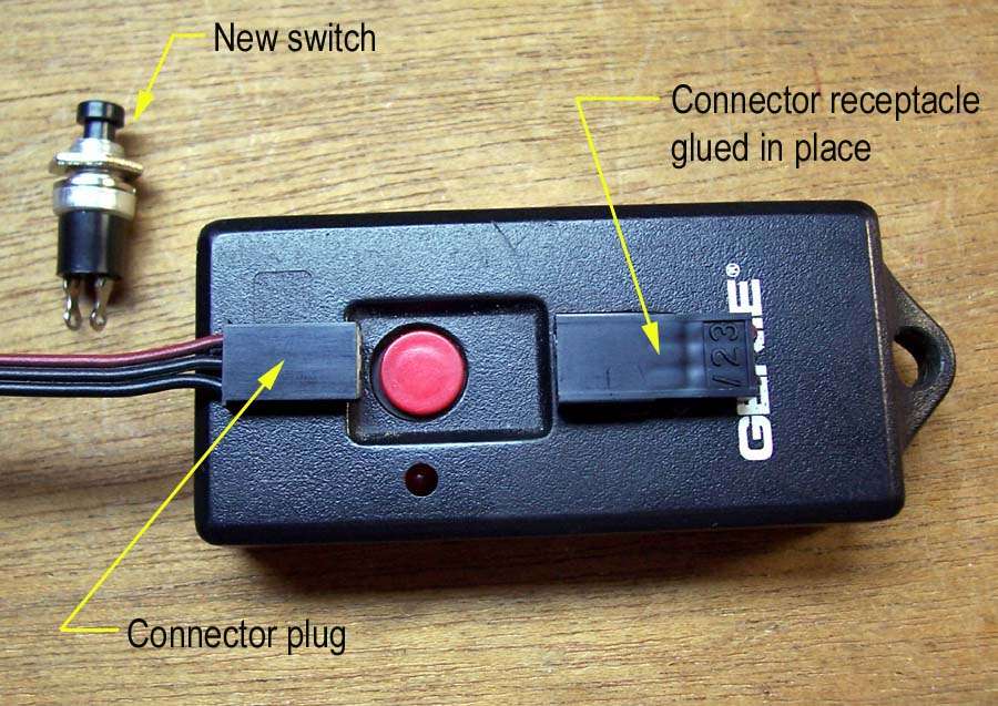
The hardest part is now over and now you should test your wiring by jumping the receptacle leads outside the case and verify the door operates as intended. Snap the case together being careful not to trap any of the wires. I glued the receptacle to the case and the modified remote is now just slightly larger than before. The plug is shown next to the receptacle along with the new switch.
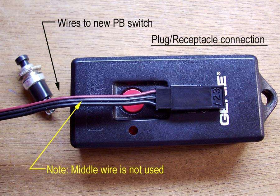
The plug end of the harness connects to the receptacle and the wires will route to the new switch. Only two wires are required for this – the middle wire in the picture is not used but provides strain relief.
Solder the new switch onto one end of a length of 2-conductor wire and cover the exposed terminals with heat shrink tubing to prevent shorts. I recommend using the continuity tester to check the new switch and wiring are working properly after soldering. The exact length depends on the final location of all components but better to have too much wire than too little. What seems like plenty can be too short once you start some creative routing along the frame as I found out the hard way. At this point I had the new switch with a 2-foot long pigtail and the remote with the new plug/receptacle assembly – two separate items to be connected after being installed.
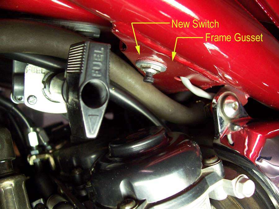
Now mount the new switch in a desirable location. I found the perfect spot on the frame under the gas tank behind the fuel lever. There was a triangular gusset with holes predrilled that matched the new PB switch almost perfectly. There was an identical gusset on the throttle side of the tank for those who prefer to use their right hand for activating the opener. I mounted the switch to the front hole, daubed a bit of goop on the threads and secured it with the nut. The goop (or silicone adhesive) insures the thing won’t vibrate loose. The wire was routed through the second hole and back along the frame to the “trunk” area. You may choose to mount the switch in a totally different spot than shown but the concept remains the same. Do one more check with the continuity tester on the pigtail wiring to check for possible damage to the switch during installation since things are a tight fit.
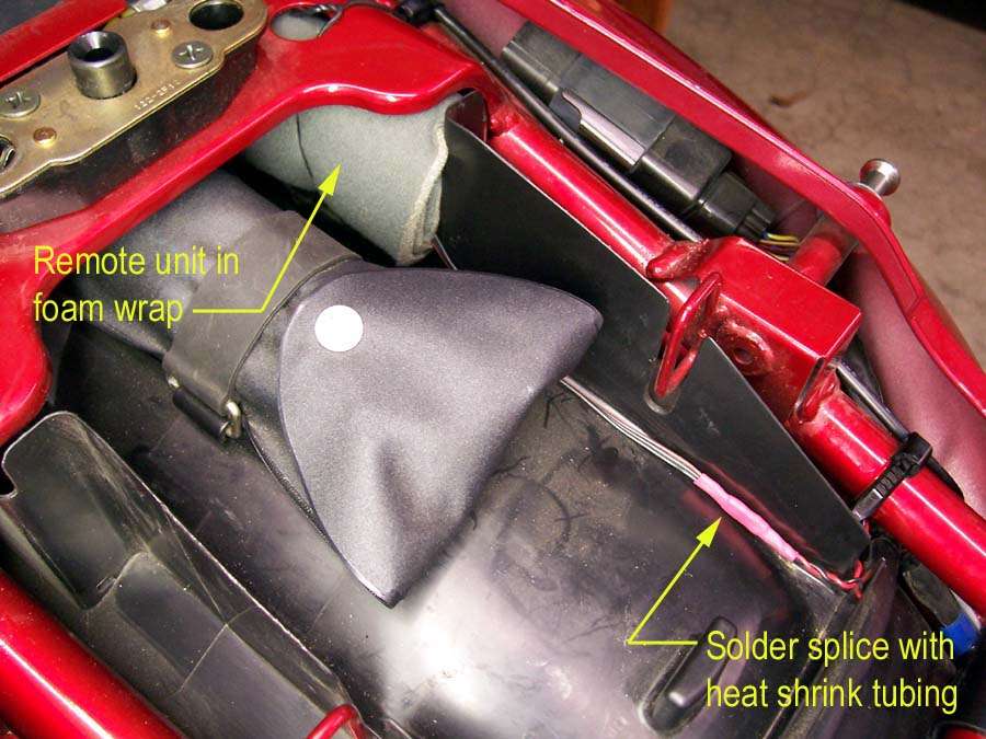
Almost finished……. Hang in there….. just need to find a good spot for the remote. After trying several places I finally located my remote unit in the rear of the “trunk” beside the tool kit. It is out of the way and routine service work can be performed without removing it. Of course that is one reason why I went to the trouble of a plug/receptacle feature – just in case it needed to be yanked out. Prior to wrapping it in foam and securing to the frame I made the last two solder joints and covered with heat shrink tubing.
The installation is now complete and a press of the button should be the final test. If there are problems recheck the battery installation, the code switches, the plug/receptacle connection and that the door has power. I have enjoyed this project and hope you will consider it for one of your future Bandit mods…it is one of the COOLEST!!!

 Topic: Christmas Present: Bandit Garage Door Opener Modification (Read 3885 times)